Robot calibration is a key part of our core competencies. We are therefore pleased to offer you a full range of services in this area.
The sigma3D team supports you in accurately determining and calibrating the static and dynamic parameters of your industrial robots in accordance with ISO standards.
To this end, the sigma3D team combines state-of-the-art measurement technology, many years of experience, and comprehensive expertise. Using our measuring equipment, we can perform measurements on-site at your production facility and determine the parameters for any type of robot. This allows us to immediately identify deviations that can be significantly improved through subsequent robot calibration using a point grid and a “look-up table” or by determining Denavit-Hartenberg (DH) parameters.
The result: highly efficient production without any loss of performance.
Take advantage of our expertise and gain greater reliability and precision for your industrial robots!
Your benefits at a glance
In the following, we’d like to use examples to illustrate the significant improvements that are possible when you take a targeted approach to the “robot calibration” project.
While repeatability is very good—within the 1/10 mm range—when maintaining the same pose, large robots in the 200-kg class can sometimes exhibit deviations of several millimeters in their absolute position within the workspace. This depends on the base structure and the weight load.
For standard tasks in which the robot repeatedly performs the same sequences, teaching these poses can be the solution. However, this can also make you a slave to the system, because every change to the product or the processes must not only be incorporated into the design or offline programming—it also requires teaching each additional position every single time. Depending on the complexity and number of poses and movements, this can be very time-consuming and therefore costly.
Ideally, the robot is made more precise—so precise, in fact, that the movements from the design are transferred 1:1 to the robot. This builds confidence in the machine that it will do exactly what the designer or offline programmer intends.
To turn this ideal scenario into reality, laser-based 3D measurement technology is used. It is the most cost-effective approach for this purpose.
This technology provides a high-level measurement system—using a laser tracker—with a measurement accuracy of 0.01 mm/m and a level of flexibility that allows for installation in virtually any environment where industrial robots are also used.
A distinction is made between two types of measurements that can be performed on or with a robot to improve its accuracy.
The goal of what is known as base surveying is to determine the robot’s own coordinate system relative to a higher-level system.
To do this, the instrument must be referenced within the plant system using the appropriate measurement software. Within this system, the robot is then moved to various positions, and a point on the robot’s tool is measured using the laser tracker. This point does not need to be recognized by the robot as a tool. The RoboCALC add-on module for the open-source software “OpenIndy,” developed by sigma3D, recognizes this “free point” and can perform the calculation. This measurement is carried out using a defined number of points within the robot’s active workspace.
The transformation parameters are determined through transformation calculations.
In particular, the rotations can be output in a wide variety of formats:
It is important to clarify in advance which format the respective robot controller supports. The data flow path must also be clarified.
In addition to the base, the tool can be simultaneously determined if the laser tracker’s measurement reflector is attached to the tool center point via an adapter.
This type of measurement is a standard procedure that sigma3D has performed—and continues to perform—thousands of times in automotive plants around the world. As a result, we have a wealth of experience in this area and follow a standardized protocol. These standards enable very short lead times.
Subject to availability, we can respond within one day.
Up to 8 robots can be measured per day without any issues (provided the necessary data is available).
The measurements mentioned above only address the robot’s overall position.
However, if the robot axes are not perpendicular to one another and the axis lengths are inaccurate, deviations will still occur during the robot’s operation. In this case, it is necessary to examine each robot axis individually.
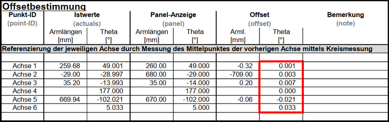
The rotational axes of the robot joints are determined using a sequential procedure. This is done by measuring individual circles, from which the central axes are determined.
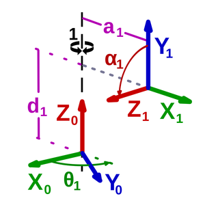
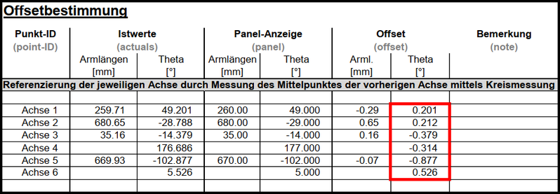
From these axes, the Denavit-Hartenberg parameters (for orthogonal axes) or the Hayati-Mirmirani parameters (for parallel axes) can be derived. Specifically, the offset of the axes and the effective arm length are determined here.
Testing the Robot After Calibration
These measurements can take approximately 6 hours per robot. Once these measurements have been successfully entered into the control system, verification tests will yield results that are at least 10 times better than those of an uncalibrated robot. It’s worth calibrating robots!
Having a good robot in operation is one thing. But its quality must also be verifiable. In addition to measurements aimed at improving the robot, it can also be tested for its “reliability.”
Key parameters for robot calibration here are absolute accuracy—also known as “accuracy of pose or path” and abbreviated as AP—and repeatability—“repeatability of pose and path,” RP.
Both AP and RP are part of the international ISO 9283 standard (DIN ISO 9283) and are therefore included in the testing. In addition to such rigorous testing of the robot according to the ISO standard, testing according to customer specifications can also be performed upon request.
After all, every application is different. For some customers, repeatability is important; for others, path accuracy is the priority; and still others prioritize speed and the interaction of various external sensors attached to the robot.
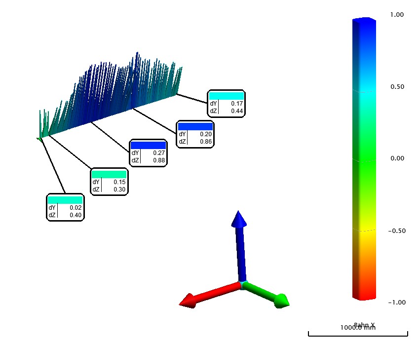
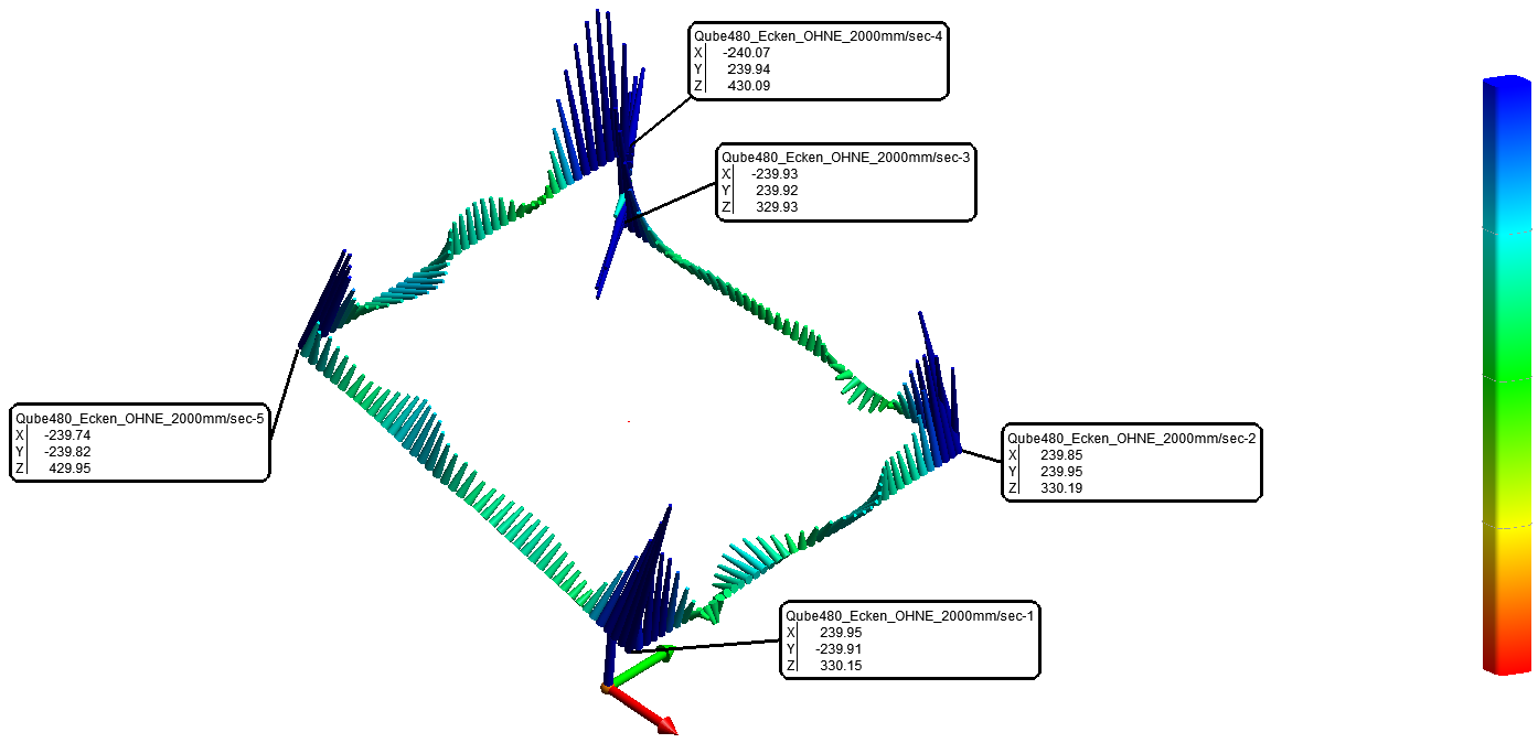
Especially when it comes to path accuracy in conjunction with speed, measurement using a laser tracker is a proven solution. Speeds of 2000 mm/sec are no problem, and the target point can still be tracked without difficulty.
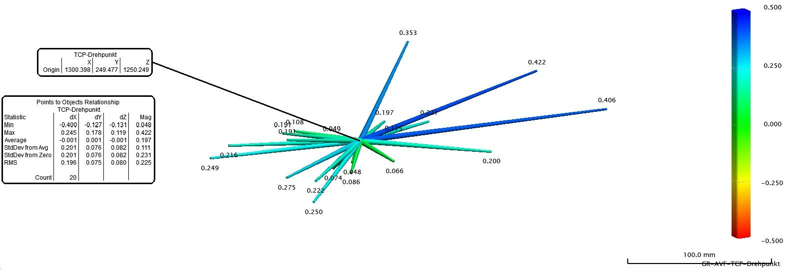
Here, for example, Spatial Analyzer serves as our measurement and analysis software. This high-end software product enables even complex analyses and quickly clarifies the current situation. Thanks to the various options for displaying deviation vectors, all measurements following a robot calibration are quickly and reliably evaluated and visualized.
Another common test item is the reorientation of the tool around a defined point. Robot operators often perform this using two measuring probes and verify the results visually.
Laser tracker measurement allows this
to be documented beyond a doubt. The dispersion of these measurement points provides a good indication of the robot’s quality within a specific working range.