
For more than 80 years, Kronos Titan GmbH (KRONOS Worldwide, Inc.) has been one of the leading producers of titanium dioxide white pigment and iron salts. The company operates production facilities in Germany, Belgium, Norway, Canada, and the United States. The rotary kilns operate continuously and are taken offline only for maintenance purposes.
CUSTOMER REQUIREMENT:
During operation, temperatures of up to 900 °C are reached inside the rotating 53-meter-long steel cylinder. To prevent damage to the steel shell, the steel pipe—which has a wall thickness of 20 mm—is lined on the inside with firebricks as a protective layer. A new firebrick lining is approximately 200 mm thick. During the firing process, the sulfuric acid contained in the titanium oxide hydrate suspension causes increased wear on the protective layer. A wall thickness of less than 80 mm is considered critical, and safety can no longer be guaranteed. The furnace must be shut down for maintenance and relined.
Since both shutting down the rotary kiln (DRO) too early and too late is economically disadvantageous, a comprehensive survey of the rotary kiln (DRO) from the outside and inside is now to be conducted to determine the remaining wall thickness and geometric shape at relevant locations.
Precise measurement of the furnace while it is shut down captures its current condition and will serve as a baseline for future measurements taken during operation. The ultimate goal is to ensure that residual wall thickness can be verified during operation in the future using other measurement methods, such as thermography, in order to predict the correct timing for the next maintenance and, consequently, the plant shutdown. Further measurements using sigma3D are intended to enable a correlation analysis between the precise scanning measurements taken during the maintenance shutdown and the less precise measurements taken during operation, thereby allowing for a highly accurate long-term prediction of the correct maintenance interval.
The prerequisites for our work and for optimal results with a DRO are:
Measurement Procedure:
Within a few days, the entire DRO surface—both interior and exterior—was fully mapped using terrestrial laser scanning (TLS) from multiple vantage points.
To link the laser scanner positions, reference markers and reference spheres were generally used.
In addition, the reference points were also determined using a laser tracker in a network survey to finally evaluate the network quality or to use as a local positioning method. This allows the laser scanner to calibrate itself very precisely into the reference coordinate system, even in hard-to-reach areas, using the reference points determined by the laser tracker.
Measurements were preferably taken at night and during the early morning hours, as the geometry would otherwise be affected by material and temperature expansions.
RESULT:
The individual scans were merged into a single point cloud and then processed in Polyworks.
In the first step, a reference contour for the current and all subsequent measurements was derived from the measurement data of the outer contour. A reference inner contour model was created based on the furnace shell thickness and the nominal brick thickness of the inner lining.
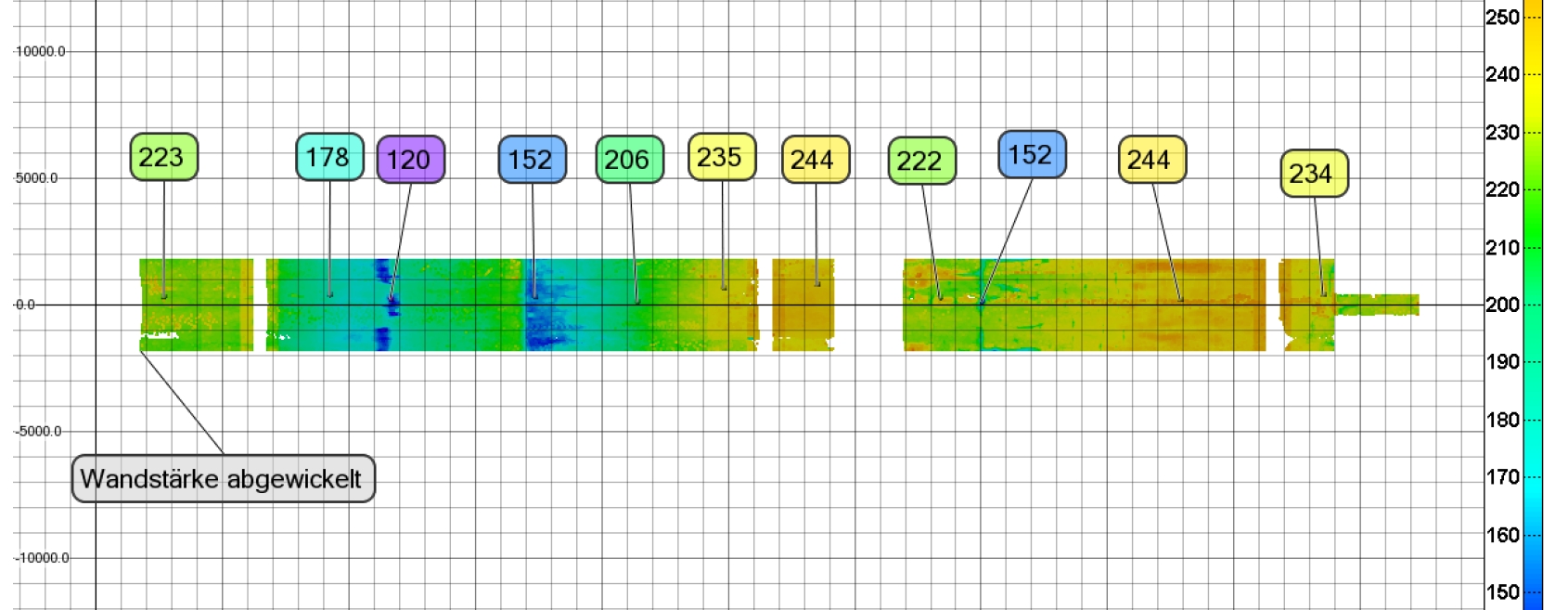
In the second step, the measurement data from the internal measurement were compared with the target internal edge model, and a 3D wall thickness model of the external contour was generated. By creating cross-sections at the desired and relevant points, the wall thickness could be visualized.
The remaining wall thickness was also displayed within the pipe shell using a color scale so that it could be visually identified.

Using the data we have provided, maintenance can now be carried out accordingly, and the relevant firebricks can be replaced.
The individual evaluations of the measurements—that is, the quality and accuracy of the grid measurement using the laser tracker, as well as the scans taken with the laser scanner—exceeded previous calculations and expectations, even when external influences and conditions were taken into account. The single-point accuracy of 3–5 mm guaranteed to the customer for each point was achieved.
The close coordination between sigma3D and Kronos Titan in the early stages, the detailed preparations, and the on-site technical support (mechanics, scaffolding, etc.) all contributed to the project’s success and to meeting the tight schedule.
We would like to thank you for the great collaboration!
If you have any questions regarding this, please feel free to contact us!