3D measurement: components, tools and products
sigma3D offers professional 3D scanning services for a wide range of contract measurements in the fields of design, production and development. From paper clips to wind turbine blades - we can measure it.
State-of-the-art optical 3D measurement technology? Experienced engineering team? In-house measurement laboratory? We have everything it takes for your precise component measurement with the highest surface requirements! With every order of our 3D scanning service, efficient and fast execution is just as important to us as 100% reliable measurement results.
Because: We know that the quality of a contract measurement directly determines the quality of your work and production as well as the compliance with standards!
As a result, you receive high-resolution scan data from us with the 3D model of your completely captured component. You can analyse these directly and use them for your individual requirements. Should your object of measurement be too large for shipping, we simply fall back on our mobile 3D measuring technology.
We will be happy to help you with any questions you may have about 3D component measurement - just get in touch with us!
Your advantages at a glance:
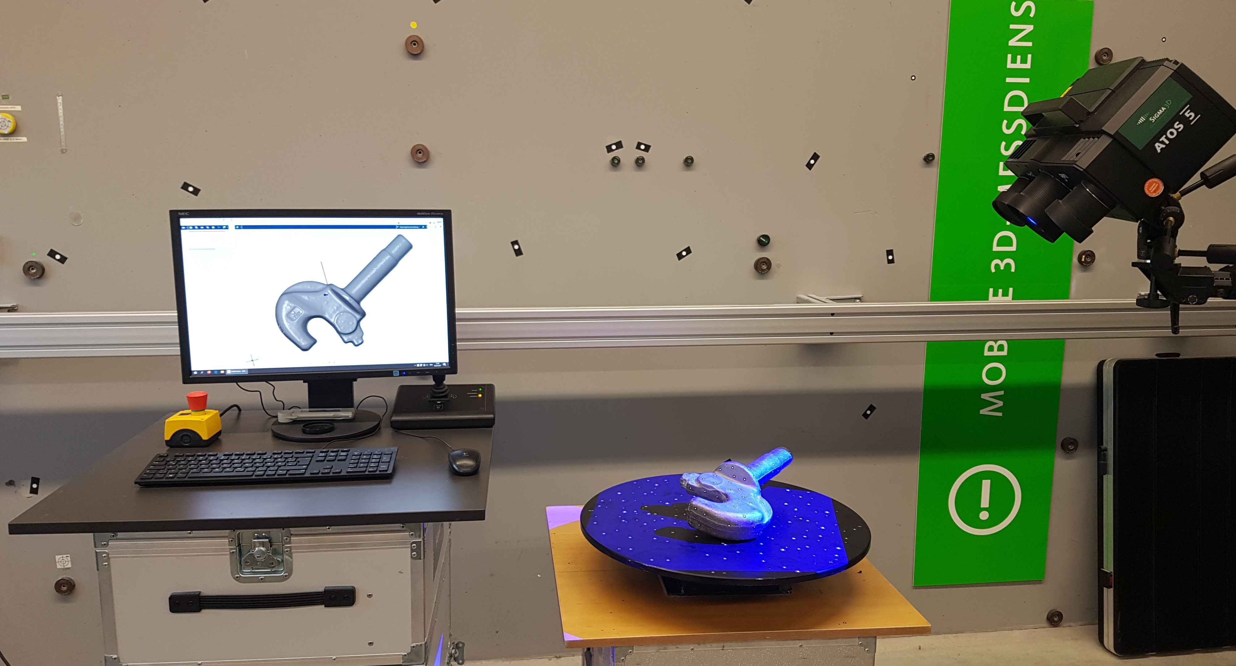
We place the highest demands on quality and precision for all subcontracting measurements. After your object has arrived at our premises, it finds its way to our in-house measuring laboratory: Here, we have special premises equipped with the latest measuring technology. In this specialized facility, the optical measurement of components, products or machine parts is carried out by our measurement team of experienced engineers.
After the optimal measuring set-up has been set up, your object is digitally recorded with a scan camera or a scan arm, depending on its size and shape. The non-contact optical 3D measurement enables an accuracy of 0.02 to 0.2 mm. In contrast to tactile measuring, the 3D scan also allows us to completely capture free-form surfaces.
In addition, we offer you the option of mobile 3D measurement: components or machines that are too large and heavy for delivery are measured by our team directly on your premises. We would be happy to advise you personally - please contact us!
In the optical 3D measurement of components, we always capture the complete object for you in order to create a digital model. This procedure has two advantages:
Advantage 1: Versatile STL data.
You receive the digitized component from us as an STL data set, a polygonal model, which you can use with our provided viewer application. This allows you to easily analyze, process and quickly share all data with employees and partners anywhere in the world.
Advantage 2: Never measure again!
At any later point in time, you can still evaluate all those areas that did not seem relevant before the component measurement. You will never again have to spend money on a contract measurement of the object.
In addition, we can provide you with a meaningful measurement report according to your individual requirements. If the 3D scanning of components should show you defects in the component, we will be happy to support you in the analysis with our many years of experience.

Automotive - Oil duct cover

Tank

Support plate

Screw conveyor

Hand

Cart nozzle

Diffuser

Hair straightener

Coupling hook
Ultrasonic sonotrode

Stator

Mould insert
In addition to maximum precision, optical 3D measurement enables one thing above all: speed. We want you to be able to use the results of your contract measurements without long waiting times. In our measurement laboratory, we therefore combine high-performance technology with years of experience and efficient processes.
In the first step, we agree the framework parameters of the measurement with you. Then, you send us your component, we take care of the complete 3D scan service, and you receive the results from us within two to five working days of receipt!
If it is a component that you need for important production processes, we will arrange a specific measurement date with you. This reduces any downtime and the associated costs for you to an absolute minimum.
Ein Bauteil, das nach Einbau nicht wie geplant funktioniert? Eine Maschine, die wegen eines abgenutzten Elements ausfällt? Eine mangelhafte Produktmusterserie, die vom Kunden abgelehnt wird?
In all diesen Fällen ist eine professionelle 3D-Qualitätskontrolle von sigma3D die Lösung, um über eine Produkt- oder Bauteilvermessung innerhalb kürzester Zeit bis ins letzte Detail zu analysieren. Finden und beheben Sie Qualitätsmängel schon vor Produktion oder Einbau – und sparen Sie Zeit und Kosten durch minimierte Montagezeiten und Testläufe.
Je nach Ihren Anforderungen setzen wir für unsere 3D-Qualitätskontrolle unterschiedliche Methoden ein, um die erfassten Ist-Daten mit Ihren Soll-Daten zusammenzubringen. Auf dieser Basis erstellen wir für Sie individuelle Analysen und Auswertungen, wie zum Beispiel Soll-Ist-Vergleich, Erstmusterprüfbericht oder Auswertung von konkreten Prüfmerkmalen. Und: Wenn Sie vor einem besonderen messtechnischen Problem stehen, finden wir mit unserer langjährigen Erfahrung garantiert eine Lösung.
Deviation analysis is one of the fastest methods of 3D quality control: Here we align our 3D scan according to your specifications and compare any dimensions of the real product and the CAD reference object. A visual false color comparison shows you the deviations in dimension and shape from the theoretical data set. The evaluation is carried out according to the DIN standard EN ISO 1101 Geometric Product Specification (GPS). For example:
, eine Kreis Bezug „B“ (X- und Z-Richtung) und ein Langloch Bezug „C“ (Z-Achse) festgelegt.")
Definition of references
Alignment via reference points (RPS alignment)

Evaluation according to DIN EN ISO 1101- GPS (Geometric Product Specification)
Evaluation of hinge holes (position tolerance)

Planar target/actual comparison
The display of the 3D deviations in a color map enables a quick visual impression.
 oder n.i.O (nicht in Ordnung).")
Surface comparison of nominal and actual values
A representation over defined surface tolerance zones enables a representation in i.O. (in order) or n.i.O. (not in order).

Deviations at defined nominal points
For a detailed analysis, comparison points allow an exact and repeatable deviation display to defined nominal points on the CAD.
These points can also be used for an SPC analysis.

Deviations at trimmed edges
Trimmed edges are evaluated using an edge point and a reference point at a defined distance from the edge. Thus, the edge, as well as the springback of the component, is evaluated.

Deviations at flanging edges
The evaluation of flanging edges is performed using an edge point and a reference point at a defined distance from the edge. Thus, the edge as well as the springback of the component is evaluated.

Overview of sections
Sections are used for a variety of evaluations. Calipers, profile gauges or gap and flush measurements.

Cut colour comparison
The display of the 3D deviations in a colour chart enables a quick visual impression.
 oder n.i.O (nicht in Ordnung).")
Cut tolerance band
A display over defined surface tolerance zones allows a display in i.O (OK) or n.i.O (not OK).

Evaluation 2D Elements - Caliper
Thus, the caliper is transferred from the workshop environment to the 3D world.

Evaluation 2D Elements - Profile Gauge
In addition to measuring constant and variable radii, profile gauges can also measure step height, tangent angle, tangent points and theoretical sharp edge points.
Thus, the profile gauge is transferred from the shop floor environment to the 3D world.
With the profile gauge, "tornado lines" can be evaluated efficiently.

Documentation in an inspection characteristics plan (PMP).
Evaluation of all inspection characteristics in tabular form.
The inspection characteristics <link internal-link>plan can be easily processed as a CSV or Excel file.
An area-based target/actual comparison is the visual representation of 3D deviations: These represent the distance between a measuring point and its associated CAD surface.
For a simple and fast 3D quality control, we display all 3D deviations in a color map for you. We can customize this representation individually, for example by color selection or defined surface tolerance zones with in-order or out-of-order markings. For a target/actual comparison, we can use different analysis methods depending on the shape and type of your measured object:
Deviations at defined nominal points: Defined nominal points on the CAD model allow an exact and repeatable deviation analysis. The results are interpretable equivalent to the measured values of a tactile coordinate measuring machine - whereby the evaluation time is independent of the number of nominal points.
Deviations at edges: We evaluate trimmed or flanged edges via an edge point and a reference point at a defined distance from the edge. Thus, the edge and also the springback of the component are evaluated.
Deviations of defined sections: Se ctions are used for a variety of evaluations and enable the functions of calipers and profile gauges as well as gap and flush measurements on the 3D model. In this way, various measuring tools can be transferred from the workshop environment to the 3D world for your 3D quality control.
Vor Beginn der Serienfertigung von Bauteilen oder Produkten gilt es, einen Erstmusterprüfbericht (kurz: EMPB) einer Erstmusterserie zu erstellen. Im Rahmen unserer 3D-Qualitätskontrolle ermitteln wir für Ihren EMPB je nach individueller Anforderung einzelne bis mehrere Hundert relevante Maße Ihrer Erstmuster.
Den finalen EMPB mit aussagekräftigen Daten zu den Ist-Werte im Vergleich zu den Soll-Werten erhalten Sie von uns in der Regel in Form einer Zeichnung. Mögliche Abweichungen innerhalb der Serie können Sie sofort erkennen und direkte Rückschlüsse ziehen, ob sie im Produktionsprozess oder an der Produktionsmaschine entstehen. Sobald der Erstmusterprüfbericht für Ihr Bauteil oder Produkt den Anforderungen der 3D-Qualitätskontrolle entspricht, können Sie ihn als Nachweis für Partner und Kunden verwenden.
Form- und Lagetoleranzen sind bei Baugruppen ein Mittel zur Festlegung der Anforderungen von Konstruktion und Zeichnung bezogen auf die tatsächliche Funktion und Beziehung. Im Zuge unserer 3D-Qualitätskontrolle werten wir alle Anforderungen entsprechen der Form- und Lagetoleranzen aus.
Dies erfolgt über geometrische Toleranz-Zonen, in denen ein gemessener Wert liegen soll. Die Interpretation der ausgewerteten Größen machen wir für Sie eindeutig und einfach: Das Ergebnis ist i.O („in Ordnung“) oder n.i.O („nicht in Ordnung“). Unsere 3D-Qualitätskontrolle erfolgt hier entsprechend DIN EN ISO 1101 Geometrische Produktspezifikation (GPS).
Die grundsätzliche Voraussetzung jeder Analyse im Rahmen unserer 3D-Qualitätskontrolle ist die Ausrichtung. Eine Ausrichtung ist die Operation, mit der die digitalisierten 3D-Koordinaten einer Punktwolke in das gleiche Ausgangskoordinatensystem – zum Beispiel einen CAD-Solldatensatz – überführt werden. Hierfür verwenden wir neben der Ausrichtung über ein Referenz-Punkt-System (RPS-Ausrichtung) als weitere Methoden „flächen-best-fit“ und die Ausrichtung über Bezüge.
Individual measurement programs for your inspection characteristics plan (PMP)
Within the scope of 3D quality control, we create measurement programs for you according to your inspection characteristics plan (PMP). Here we bring together engineering knowledge and enormous application competence for you.
Thanks to external programming by us with the Polyworks Inspector measuring program, you benefit from our experience in developing effective evaluation strategies. The evaluation is carried out according to the DIN standard DIN EN ISO 1101 GPS (Geometric Product Specification).
")
Day 1: You pack the component and send it to us.

Day 2: The component arrives at our premises by 10.00 a.m. and is handed over to our measurement laboratory for optical 3D measurement.

Day 3: You receive your object back via a retrieval order and receive the results of our wage measurement from us.

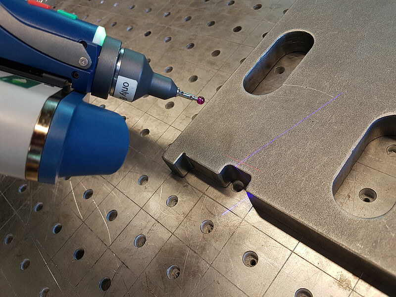
Quality Control: Waterjet Cutter & Plasma Cutter
What added value did the component measurement have for our customer? Thanks to the 3D measurement of components of his waterjet cutters and plasma cutters, our customer received complete and meaningful data for his quality control. In a so-called section analysis, he was able to evaluate each area of the trim against his target data. Based on this analysis, the cutting parameters could be adjusted quickly and in a time-saving manner. The effect: Optimal and precise cutting results.
The customer is also able to minimize the steps required to adjust the cutting parameters thanks to our 3D scanning service, thus saving valuable time and money.
What was measured? Our engineers are performing a cut contour measurement for plates from waterjet cutters and plasma cutters. The plates had a size of 60 x 30 x 3 cm - ideal for component measurement directly in our measurement laboratory.
How long did the component measurement take? After delivery and measurement setup, the plates were scanned precisely and completely within one day.
What optical measurement technology did we use? For the optical 3D measurement of the plates, our ScanArm was used to capture the complete trim. Geometric features such as drill holes and slotted holes were also measured tactilely.
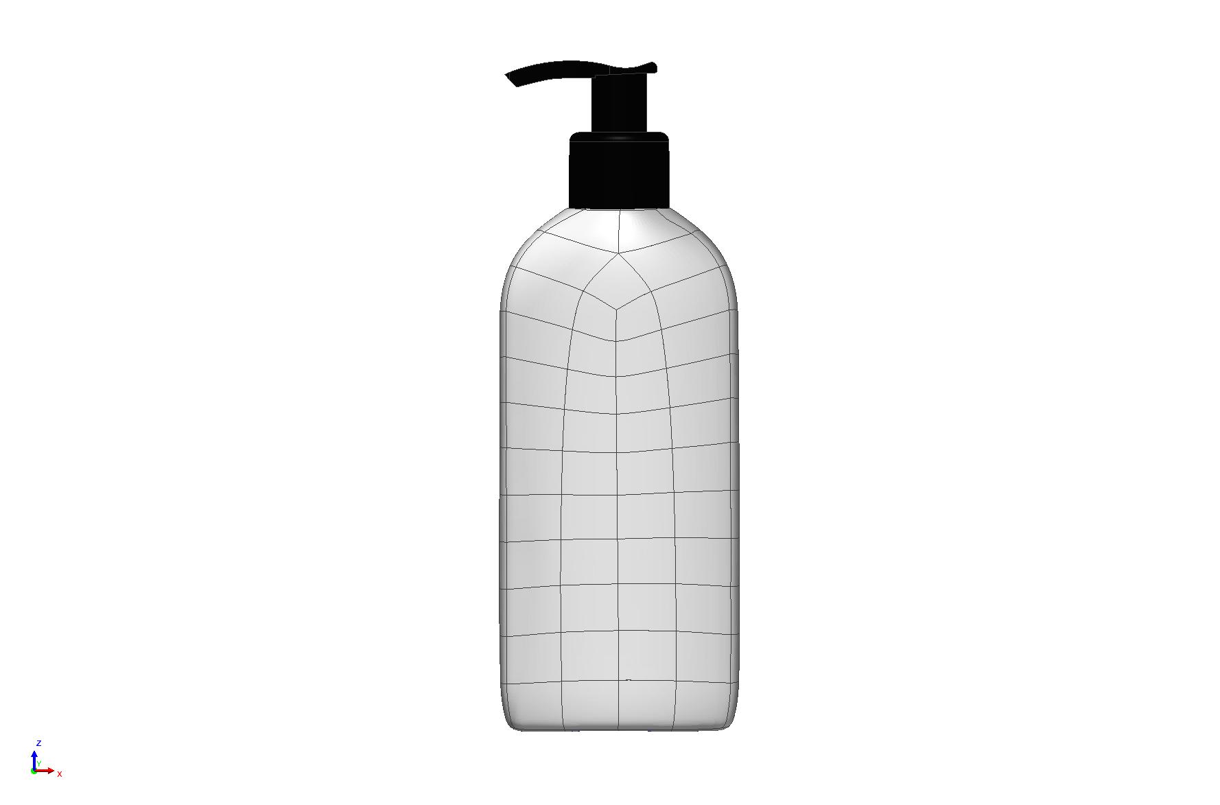
Surface feedback: Packaging machines for bottles
What added value did the component measurement have for our customer? Finished bottles of washing-up liquid and shampoo are to be packed in cartons for transport and dispatch. However, our customer did not have any CAD data to be able to plan the packaging machine for the different bottles at an early stage.
With our 3D scanning service, we were able to quickly and easily scan the "components", obtain precise measurement data and generate all the necessary CAD models. This allowed our customer to plan their packaging machine virtually and eliminate the need for lengthy and costly on-site adjustments. Our service saved the customer a lot of time and money.
What was measured? The measurement of bottles for the planning of packaging machines was an order from a typical field of application for 3D measurement: mechanical engineering. With a size of only 10 x 15 cm, the bottles were easy to measure in our measuring laboratory.
How long did the component measurement take? Due to the simple shape and small size, the bottles could be scanned within one day.
What optical measurement technology did we use? We used our ScanKamera for the optical 3D measurement of the surfaces of consumer goods such as bottles.