
In recent times, the hobby of model railroading has experienced a rapid upswing. For serious model railroaders, however, the acquisition of new vehicles is not at all in the foreground, but the new construction or also the modification of existing series vehicles.
That is exactly what Mr. Beylich does. He is a member of a club that supports the preservation of old model railways from the former GDR.
"The modification of existing series vehicles was also the reason for the project described here in nominal size TT (scale 1:120). The double-decker trains offered by the industry (Berlin TT railways) were produced from the 60s onwards until after the reunification. They represent the prototype from the 60s and are also technically at this level. While there were further developments e.g. in the nominal size H0 (scale 1:87), these were missing for the size TT, although many model railroaders of this section would have wished it. That was the reason why I decided to close this gap and to start with a small series of the double-decker trains built in the late 70's", says Mr. Beylich about his work.
For the exact reproduction, the model trains are to be scanned and CAD data created. On the one hand, car windows are to be reproduced from these data, and on the other hand, fronts of a younger type of car are to be redeveloped. In both cases, the 3D models created by sigma3D formed the basis for the production.
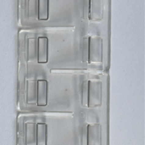
The new carriage windows are to be replaced and renewed according to the existing carriage windows. The challenge here is the high accuracy, as the new windows are to fit into the existing recesses of the carriages.
The required tolerance of ±0.05mm for the newly manufactured components must therefore be adhered to and the scan of the components must be carried out with the corresponding precision. Therefore, the GOM ATOS 5 measuring system with a 170mm measuring field and an accuracy of less than 0.005mm sphere distance deviation was used. Due to the transparency of the car windows, they were sprayed with a spray powder (titanium oxide) before scanning to guarantee a precise measurement result.
The data of the scan with the ATOS 5 form the basis for a precisely fitting reconstruction (reverse engineering). The scan data was converted into a CAD model in step format for further processing and forwarded to the tooling company for production of the injection mould. For further processing, the window frames were printed by the company Herzog-Industriedruck. sigma3D provided the corresponding data to Herzog-Industriedruck for a smoother process.
In the injection moulding process, liquefied plastic is pressed under pressure into the cavities of a mould. The geometries of the cavities reproduce the shape of the component, which is how the components are produced. CAD data of the respective component, in this case the car window, is required for the production of the tool.
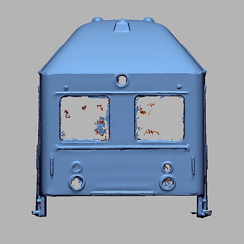
Another task is the modeling of the front of the car of the railway model from 1975. The special thing here is that this railway model never existed as a model railway. Therefore, the model is to be adapted from the existing older model years in such a way that it can be glued onto an old model series in a modified form. Since there is no template for the development of the front of the car, only an indirect approach to data acquisition came into question. As in the first part, the components, this time the cars, were scanned with the GOM ATOS 5 scanner. Afterwards, the front and rear car fronts of the existing year of construction were reconstructed, whereby even the finest details such as power cables running along the outside were modeled.
Afterwards the detail differences of the successor model (changed windows, footboard, grab rail) were constructively introduced. The information for this was provided by the customer. On existing photos of the subsequent year of construction, he took a professional look at the differences and extracted the dimensions of the corresponding components. With the help of the scaling factor, the modified geometries were then modelled in the appropriate dimensions and exported as a CAD model. On this basis, the carriage fronts are now printed using a 3D printer and then attached accordingly.
Since this project requires a high printing accuracy, the more common but also cheaper FDM process is not used here in favor of the finer SLA printing. In the 3D printing process using FDM printing, heated plastic is sprayed in layers onto a plate from a fine nozzle. These layers then add up to form the component.
The finished components, i.e. the carriage windows, as well as the fronts have now been installed in the existing carriage parts and we are pleased to hear that everything fits as planned.